System Architecture
(INFT12-212 and 72-212)
Lab Notes for Week 6: System Calls, Interrupts and
Context Switching
1 Introduction
In this, the last lab on assembly programming, we are going to look
at two things: how to write a system call handler, and how the CPU
can context switch between two programs that wish to run.
2 A System Call Handler
We start with an example of a system call handler. Last week, we saw
how to poll the Keyboard and Display Simulator device registers so
that we could send and receive characters. In this example, we introduce
two new system calls:
| Syscall | Name | Purpose |
|
| 104 | myprint_string | Like print_string, but using the Display |
| 108 | myread_string | Like read_string, but using the Keyboard |
Now, a user-mode program is technically not allowed to access the
Keyboard and Display Simulator device registers directly, so the proper
way to do I/O on this device is to create some new system calls which
hide the actual I/O but provide a nice API. Therefore, we now have
two new syscalls, 104 and 108, which work exactly like print_string()
and read_string(), but they use the Keyboard and Display Simulator.
To demonstrate this, we need two assembly files:
- A user-mode program which makes the system calls.
- A kernel-mode system call handler which does the work.
In the following tasks, we load both files and them run them together.
2.1 Task 1
This task requires a bit of set-up, so make sure you follow the instructions
below carefully.
- Download this file, but for now do NOT load it into the MARS
simulator: wk6syscall_handler.asm.
- Using the instructions from lab 5, set the instruction
handler to wk6syscall_handler.asm.
- Download this program wk6use_new_syscalls.asm,
load it into MARS and assemble it.
- Turn on Tools -> Keyboard and Display Simulator. Connect the simulator
to MARS and do a Reset, just in case.
- Now you should be able to run the program. The program prints a prompt
string to both the Display Simulator and the MARS console. You get
to type in a line of text followed by the Enter key. Finally, the
program re-prints your line of text to both the Display Simulator
and the MARS console.
If you want to run the program several times, it is usually a good
idea to reset the Keyboard and Display Simulator each time.
2.2 Task 2
If you look at wk6use_new_syscalls.asm, it is a pretty normal
user-mode program using system calls, except that some of them are
repeated to show that the new syscalls work just like the old ones.
The complicated file to look at is wk6syscall_handler.asm,
so we will do it in stages.
- There is the syscall handler code, which goes from the handler:
label to the eret instruction.
- There is a function called myprint_string(). It's been written
just like an everyday function, including doing the stack frames and
such. That's because even kernel-mode code should be written just
like normal. What it does is polls the send control register until
a new character is ready, and sends a character. This is repeated
for all the characters in the input string.
- There is a second function called myread_string(). Again,
it's a normal function which runs in kernel mode. Again, it polls
the read control registers, reads characters when they are there,
and fills the input buffer with characters.
The important thing to note here is that all the code so far is normal
code, and it could even have been translated from a high-level language
like C or Java. When we write the code for an operating system, we
write as much as possible in the normal way.
The only code which has to be hand-written in assembly code is the
actual system call handler, i.e. the code from handler: down.
It does the same sort of thing that we saw last week:
- Save the $at register
- Determine if this is a syscall, and exit() if not. In real
code, we would kill the running program.
- If it's syscall 104, do a jump and link to myprint_string(),
and then fall into the restore: code.
- If it's syscall 108, do a jump and link to myread_string(),
and then fall into the restore: code.
- On restore, reload the $at register. Increment the saved PC value,
so we skip the syscall instruction that got us here.
- Reset the special registers that say we are dealing with a system
call, and eret to return to user mode.
The whole point of this example is that it demonstrates that we can
write our own system call handlers in MARS, but we do need to deal
with the events surrounding the system call, i.e. the change from
user mode to kernel mode and back again.
3 Multitasking and Context Switching
The last thing to look at is context switching, where multiple programs
take turns using the CPU to run instructions. For this example, we
need:
- Two user-mode programs. In this mini-example, both will be in the
one assembly file.
- A source of periodic interrupts known as clock ticks, so that
we can regularly get to kernel mode and make the context switch.
- An interrupt handler which catches the clock tick interrupts and does
all the hard work.
3.1 Task 3
This task requires a bit of set-up, so make sure you follow the instructions
below carefully.
- Download this file, but for now do NOT load it into the MARS
simulator: context_switcher.asm.
- Using the instructions from lab 5, set the instruction
handler to context_switcher.asm.
- Download this program wk6multitasking.asm,
load it into MARS and assemble it.
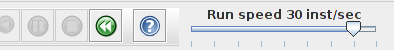
- Lower the run speed from no interaction to 30 instructions per second.
- Select Tools -> Digital Lab Sim from the MARS menu bar. This is the
device which will send the clock ticks.
- You should see a new window appear. Click the "Connect to MIPS"
button in the window.
- Finally, run the wk6multitasking.asm program. You should see
this sort of output:
In main1, the counter is 0
In main1, the counter is 1
In main2, the counter is 10000
In main2, the counter is 10002
In main1, the counter is 2
In main1, the counter is 3
In main1, the counter is
In main2, the counter is 10004
In main2, the counter is 10006
In main2, the counter is 100084
In main1, the counter is 5
In main1, the counter is 6
In main2, the counter is 10010
In main2, the counter is 10012
3.2 A Look at Both Files from Task 3.
Let's now look at both of the files from the above task, to see what
is going on. The wk6multitasking.asm file looks like a normal
program with three functions: main(), main1() and main2().
main1() and main2() are pretty simple. Each one prints
out a counter, increments it, and loops back. In fact, both of them
are infinite loops. Also note that main1() never calls main2()
and vice versa. But from the output above, it is quite clear that
the CPU is switching between both functions, even though there is
no code in this file to do that!
Even more interesting, the main() function performs a new syscall,
100, and then exit()s afterwards. So how does the CPU get to
run the main1() and main2() functions, if there is no
branch or jump from main()?
The answer is, of course, that we are getting the CPU to context
switch between the two programs. This requires a periodic interrupt
known as a clock tick to arrive. The clock tick is handled
by an interrupt handler which saves the state of one program, reloads
the state of the other program, and returns to the other
program, i.e. not back to the program which was running when it was
interrupted!
3.3 The Syscall 100 Handler
Now let's look at the code in the context_switcher.asm file.
In order to save the state of each program, we need a Process Control
Block (or PCB) for each program. This has enough space to store all
the registers that the program uses. In a real operating system, the
PCB for MIPS would be at least 32 words in size, one for each of the
32 registers. Here, we only need space to save 5 of them:
   # Define a process control block for each program
           .kdata
   p1pcb:  .space 20       # Room for a0, v0, t0, t1 and PC (offsets 0, 4, 8, 12, 16)
   p2pcb:  .space 20       # Ditto
At the top of the assembly code in this file is the generic front-end
code to determine if we are dealing with a system call or an interrupt,
which we are going to ignore and move down to the system call handler
at the label syscallhdlr.
When we get syscall 100, the user-mode program has given us the address
of the first instructions for two programs that we want to context
switch between. The system call handler simply sets up initial values
for all the registers for each program in its PCB. The main()
program has sent us the addresses of main1() and main2(),
so the PCBs are set up as follows:
| Program | $a0 | $v0 | $t0 | $t1 | Program Counter |
|
| 1 | 0 | 0 | 0 | 0 | main1()'s address |
| 2 | 0 | 0 | 0 | 0 | main2()'s address |
With that done, the handler can enable the clock tick interrupts from
the Digital Lab Sim window, and then jump to the code which restores
the registers from the PCB and restarts one of the programs. This
has the effect of starting one of the programs, and hence
the syscall never returns back to the main() program!
3.4 The Clock Tick Interrupt Handler
The interrupt handler has 4 main things to do:
- Save all the registers into the current PCB as quickly as possible,
before they are destroyed.
- Change over to the other PCB.
- Load all the registers from the new PCB back into the CPU.
- Do the eret instruction, which returns from kernel mode back
to user mode, to the instruction that was being performed by that
program when the last interrupt came in.
There's a few more things to do, like re-enabling the interrupts which
were disabled when the handler started up (we don't want to be interrupted
when we are dealing with an interrupt, do we?), and also resetting
values in the co-processor registers, but the important actions are
the 4 listed above.
Graphically, we can visualise where the CPU is executing instructions
as time progresses with this diagram:
3.5 Task 4
Read through the code in both files, and make sure that you can relate
the assembly instructions you see to the description above. You are
not going to be expected to write your own context switcher, but you
are expected to gain a good appreciation of what has to be done by
the context switching code.
One question you should ask at this point is: does context switching
take CPU time away from the programs? The answer is, definitely yes!
There are about 30 instructions in the context switching code, and
some are pseudo-instructions, so count that as probably closer to
40 real instructions. Imagine if, on average, a program got to execute
60 instructions between starting up after the eret and before
the next interrupt arrived. So, out of 100 instructions, 60 were useful
ones, and 40 were overhead instructions just to switch to another
program. 40% of the instructions the CPU is doing are not actually
running any of the programs' code. For efficiency reasons, it makes
sense to make the delay between clock ticks much longer than the time
taken to process them.
3.6 Task 5
Look at the output from the two programs. Can you explain why there
is some output from both of the programs on the same output line,
e.g.
    In main2, the counter is 10006
    In main2, the counter is 100084
    In main1, the counter is 5
3.7 Task 6
Go back and rerun the program again, and see the CPU switching between
the two programs. While this is happening, go into the Digital Lab
Sim window and click on "Disconnect from MIPS". When the interrupt
handler returns back to one of the running programs, this program
will keep running indefinitely, because you have turned off the interrupts
which the Digital Lab Sim window is sending into the MIPS CPU.
Now, re-enable interrupts by clicking on the "Connect to MIPS"
button. The program should get interrupted, and the system will resume
its original context switching behaviour.
4 Outlook for the Next Lab
In the next lab, we will begin our operating system labs.
File translated from
TEX
by
TTH,
version 3.85.
On 12 Jan 2012, 16:01.