12th April 2019, updated 15th April 2019
These are my notes which I've made after playing with a couple of 74LS593s on a breadboard. Hopefully these are useful if you are also considering using them. Please also have a look at my second set of notes where I manage to get the chip to work.
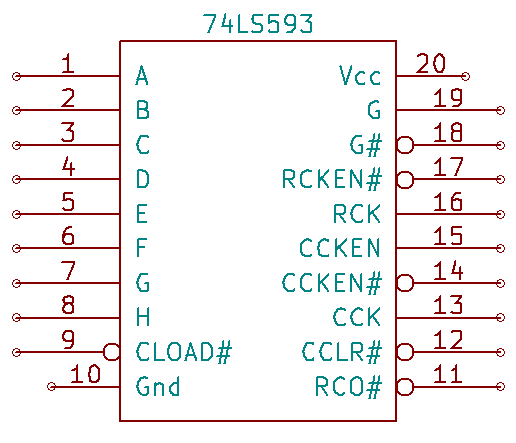
The 74LS593 is an 8-bit binary counter with an input register. It also has a carry in and carry out, and the counter's output is tri-state. This makes it ideal to be connected to an address bus where it can increment, output its value to the address bus and also load (jump to) a new value asserted by another device on the address bus.
The datasheets are confusing and, in some cases, wrong. I've tried to make some of the details a bit clearer here. Here are the links to the datasheets first:
| Pin | Name | Purpose | Pin | Name | Purpose |
|---|---|---|---|---|---|
| 1 | A | Data | 20 | Vcc | Power |
| 2 | B | Data | 19 | G | Enable counter output |
| 3 | C | Data | 18 | G# | Enable counter output |
| 4 | D | Data | 17 | RCKEN# | Enable register loading |
| 5 | E | Data | 16 | RCK | Load register when rising edge |
| 6 | F | Data | 15 | CCKEN | Enable counter incrementing |
| 7 | G | Data | 14 | CCKEN# | Enable counter incrementing |
| 8 | H | Data | 13 | CCK | Increment counter when rising edge |
| 9 | CLOAD# | Load counter | 12 | CCLR# | Clear counter |
| 10 | Gnd | Ground | 11 | RCO# | Carry output |
G and G# control the output of the counter on to the left-hand pins A to H. The two datasheets differ in how these lines work and, after trying them out, it turns out that the SGS datasheet is wrong. In fact, both lines have to be set before the output is enabled:
| G | G# | Function |
|---|---|---|
| L | L | Pins A-H are tri-state |
| L | H | Pins A-H are tri-state |
| H | L | Pins A-H output is enabled |
| H | H | Pins A-H are tri-state |
G has to be high and G# has to be low to enable the output of the counter's value on pins A-H.
These lines have no effect on the register.
When CCLR# is low, the counter is reset to zero. Otherwise, keep it high.
CCKEN and CCKEN# enable the counter to increment on a rising CCK edge.
| CCKEN | CCKEN# | CCK | Function |
|---|---|---|---|
| H | X | Rising edge | Counter increments |
| X | L | Rising edge | Counter increments |
| L | H | X | Counter does not increment |
The register comes before the counter, so you need to load the register first, then transfer the register into the counter.
The only time that the register is loaded from pins A to H is:
| RCKEN# | RCK | Function |
|---|---|---|
| L | Rising edge | Load register from pins A to H |
I would assume that you should set G and G# appropriately so that the counter's output is not enabled on pins A to H.
This pin is confusing. The SGS-Thompson datasheet says that when CLOAD# is low the data of Q bus (i.e. pins A-H) are loaded into the counter. But the logic diagram in both datasheets shows that CLOAD# controls the loading of the counter from the register, not pins A to H.
Therefore, to get a new value into the counter (i.e. to load the PC), you would need to:
And throughout this keep CCKEN and CCEN# low and high, respectively, to ensure the counter does not increment.
The TCO# pin goes low when the counter increments from 0xFF to 0x00. Therefore, if you need a 16-bit or larger counter, you can connect TCO# from the low-order 74LS593 to the CCKEN# pin of the next-order 74LS593.
I'm redrawing the truth table from the SGS-Thompson datasheet with the input pins in pin order, after playing with the chips on a breadboard.
| CLOAD# (9) | CCLR# (12) | CCK (13) | CCKEN# (14) | CCKEN (15) | RCK (16) | RCKEN# (17) | G# (18) | G (19) | Function |
|---|---|---|---|---|---|---|---|---|---|
| X | X | X | X | X | X | X | L | L | Pins A-H are tri-state |
| X | X | X | X | X | X | X | L | H | Pins A-H are enabled |
| X | X | X | X | X | X | X | H | L | Pins A-H are tri-state |
| X | X | X | X | X | X | X | H | H | Pins A-H are tri-state |
| H | L | X | X | X | X | X | X | X | Counter is reset to zero |
| L | H | X | X | X | X | X | X | X | Counter is loaded from register |
| H | H | Rise | X | H | X | X | X | X | Counter is incremented |
| H | H | Rise | L | X | X | X | X | X | Counter is incremented |
| H | H | Drop | X | H | X | X | X | X | Counter is not incremented |
| H | H | Drop | L | X | X | X | X | X | Counter is not incremented |
| H | H | X | H | L | X | X | X | X | Counter is not incremented |
| X | X | X | X | X | X | H | X | X | Register value is not changed |
| X | X | X | X | X | Drop | L | X | X | Register value is not changed |
| X | X | X | X | X | Rise | L | X | X | Register is loaded from pins A-H |
Now have a look at my second set of notes where I manage to get the chip to work.