Week 2 Tutorial - Building an ALU
1 Introduction
- This week, we are going to build an Arithmetic Logic Unit from scratch,
using a handful of simple logic gates and other components.
- The ALU will take in two 32-bit values, and 2 control lines. Depending
on the value of the control lines, the output will be the addition,
subtraction, bitwise AND or bitwise OR of the inputs.
- Schematically, here is what we want to build:
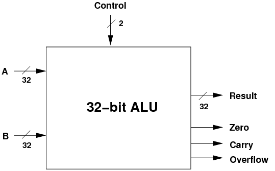
- Note! This is an interface for the ALU: what goes in, what
comes out. It also shows the ALU as an abstraction: you can't
see how it works, but you do know what it does.
- Also note that there are three status outputs as well as the main
result: is the result zero, was there a carry, and did the operation
result in an overflow?
- Note: just a reminder on the difference between a carry and an overflow:
- Carry: was there a carry in the most-significant bit which
we could not output in the given number of bits (32 bits, above).
- Overflow: does the sign of the output differ from the inputs,
indicating (for example) that a sum of two positive numbers has overflowed
and is now a negative result!
- Some of the data and control lines are shown with a slash and a number
like 32.

- This indicates that the line is actually 32 lines in parallel, e.g.
the result is 32-bits wide. If you don't see a slash in the diagrams
below, you can assume that the line is only 1-bit wide.
1.1 Basic Components
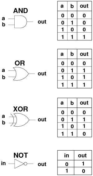
- We are going to use four logic gates: AND, OR, NOT and XOR. You should
have seen these already in other subjects. Below are the icons for
each, and their truth table.
- We are going to use another component, the multiplexor. The
job of the multiplexor is to choose one of several inputs, based on
a control line, and send the chosen input to the output.
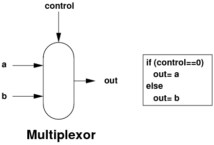
- This multiplexor above is a 1-bit wide 2-way multiplexor: 2 inputs,
1 bit wide each. If you add extra control lines, you can choose more
inputs: 2 control lines is used in a 4-way multiplexor, 3 control
lines in an 8-way multiplexor etc.
- And by using multiple multiplexors in parallel, you can make N-bit
wide multiplexors.
- I'm not going to show you the internals of the multiplexor. You should,
however, know that it can be easily built with the 4 logic gates above.
1.2 Bitwise AND
- Bitwise AND is very useful, for example to calculate an IP network's
identity:
- 131.245.7.18 AND 255.255.255.0 => 131.245.7.0
- Building the logic to do 32-bit AND on two inputs is easy: as each
bit is independent, we just need 32 AND gates in parallel.
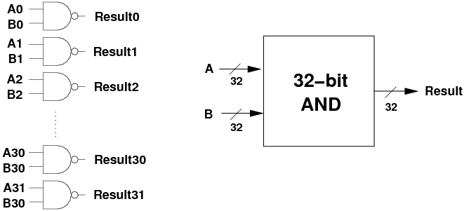
- Note the interface diagram on the right. Each time we build a larger
component, we are going to hide it behind an interface.
1.3 Bitwise OR
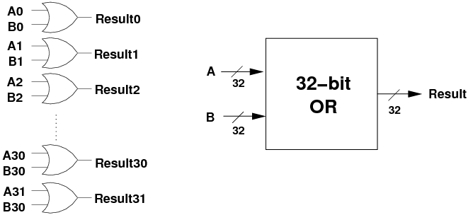
- 32-bit bitwise OR is just as easy as bitwise AND, we just need 32
OR gates in parallel.
1.4 Addition
- Addition isn't going to be so easy.
- We saw previously that we have to add bits, and this may produce a
carry. Columns further up need to accept a carry as input, along with
two inputs, and produce the 1-bit output and another carry for the
next column up.
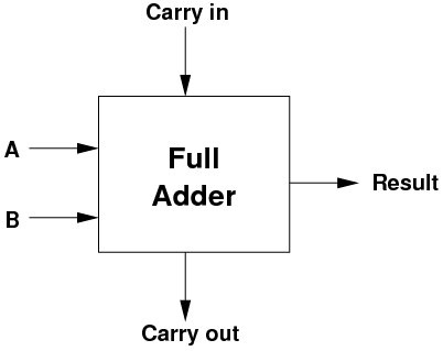
- The component which will perform a 1-bit ADD, receiving a carry in
and producing a 1-bit output and a carry out is called a full
adder. Its interface looks like the following:
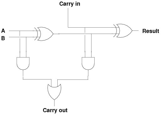
- Internally, here is what a full adder looks like, just 5 logic gates.
- The truth table for the full adder is:
| Cin | A | B | Result | Cout |
|
| 0 | 0 | 0 | 0 | 0 |
| 0 | 0 | 1 | 1 | 0 |
| 0 | 1 | 0 | 1 | 0 |
| 0 | 1 | 1 | 0 | 1 |
| 1 | 0 | 0 | 1 | 0 |
| 1 | 0 | 1 | 0 | 1 |
| 1 | 1 | 0 | 0 | 1 |
| 1 | 1 | 1 | 1 | 1 |
- At some point sit down, try some inputs, and convince yourself that
the logic works as advertised!
- To make a 32-bit full adder, we simply have to string 32 of these
1-bit full adders together.
- Except for the least-significant adder, each one is going to receive
its carry from the one below and pass up its own carry to the one
above.
- For the most significant bit, if the carry is a 1, then we ran out
of bits to store the result.
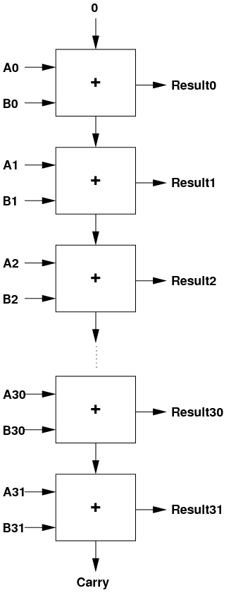
- When the final carry output is 1, this indicates that the result was
too big to fit into 32 bits.
- I'm going to delay showing you the interface diagram for the 32-bit
full adder, because we can modify it to also do subtraction.
1.5 Subtraction
- We could build a completely separate component, a 32-bit subtractor,
once we work out how to build a 1-bit subtractor.
- Fortunately, we can simplify things a bit.
- According to the rules of maths: 3-2=3+(-2).
- If we could negate one of the inputs, we could use the existing 32-bit
full adder.
- We have already seen two algorithms to negate a twos complement binary
integer.
- One of them works as follows: invert every bit in the number, then
add 1.
- Putting all of the above together, we can say:
A - B = A + (-B) = A + ~B + 1
- Inverting every bit is easy: we can use a NOT gate for each bit in
B.
- But now we need to do A + ~B + 1. How can we do this?
- We are going to use a very clever trick.
- Set the initial carry-in to 1 instead of 0, thus adding an extra 1
to the sum.
- And instead of using NOT gates, we will use XOR gates.
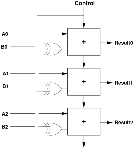
- If we are doing addition (Control=0), then one arm of the XOR gates
is zero, and the B bits go into the adders unchanged, and the carry-in
is zero.
- If we are doing subtraction (Control=1), then one arm of the XOR gates
is one. This inverts all of the B bits before they get to the adders.
As well, the carry-in is now 1, so we achieve the result of doing
A - B = A + ~B + 1!
- Overall, we end up with this unit which can do addition and subtraction:
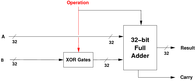
- If the operation bit is 0, we pass in B and perform A+B. If the operation
bit is 1, we invert B and do A + ~B + 1.
- We can now distinguish between data lines (which pass data
around) and control lines (which control the actions of the
components).
- The data lines are also known as datapaths.
- The Operation line above is a control line, as it controls
the action being performed. But note, it is also used as a 1-value
for the carry-in, so it is also a piece of data!
1.6 Overflow Output
- We've seen that a carry occurs when the final addition or subtraction
is too big to fit into 32 bits.
- A related mathematical output is overflow. This indicates that
the sign of the maths result differs from the sign of the two inputs.
- Imagine we were using 4-bit numbers: you do 7 + 7 and get the result
-2!
- Why? Because 7 (0111) + 7 (0111) = 1110, which in 4-bit twos-complement
is -2.
- Overflow occurs when the size of the inputs is such that there is
a carry which changes the most-significant sign bit.
- The ALU will always output both carry and overflow, but both only
makes sense when the operation is add or subtract.
- When we are doing the logical operations (AND and OR), the values
on the carry and overflow outputs have no meaning.
- As overflow is only maths related, this should be implemented in the
ADD/SUBTRACT unit.
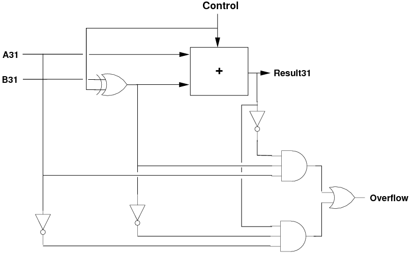
- The logic is follows: when adding, if the sign of the two inputs is
the same, but the result sign is different, then we have an overflow.
- The boolean expression is [`a31]·[`b31]·result31+a31·b31·[`result31].
- We have to do this only for addition, so we take the b31 value after
the XOR gate, i.e. just as it goes into the most-significant adder.
1.7 Negative Output
- When is the result negative? When its most-significant bit is 1.
- We can wire this bit directly out of the ALU, so that it indicates
if the result is negative.
1.8 Zero Output
- One thing left to do is to provide the zero output: is the result
zero?
- This is only true if all of the bits of the result are zero.
We can do this for the logical and the maths units.
- To do this, we can use a 32-bit OR gate followed by a 1-bit NOT gate:

- The OR gate outputs a 0 only if all input bits are 0. If any input
bit is a 1, the OR's output is a 1.
- The NOT gate simply inverts this, giving the result:
- if any result bit is on, the output is 0, i.e. not zero.
- if all result bits are off, the output is 1, i.e. zero.
1.9 Putting It All Together
- We are getting close to being able to build the full ALU.
- We now have three main units:
- a 32-bit bitwise AND unit,
- a 32-bit bitwise OR unit, and
- a 32-bit ADD/SUBTRACT unit with a control line.
- the logic to output carry, overflow, zero and negative.
- We can pass the inputs A and B to all three units, and perform all
three operations in parallel:
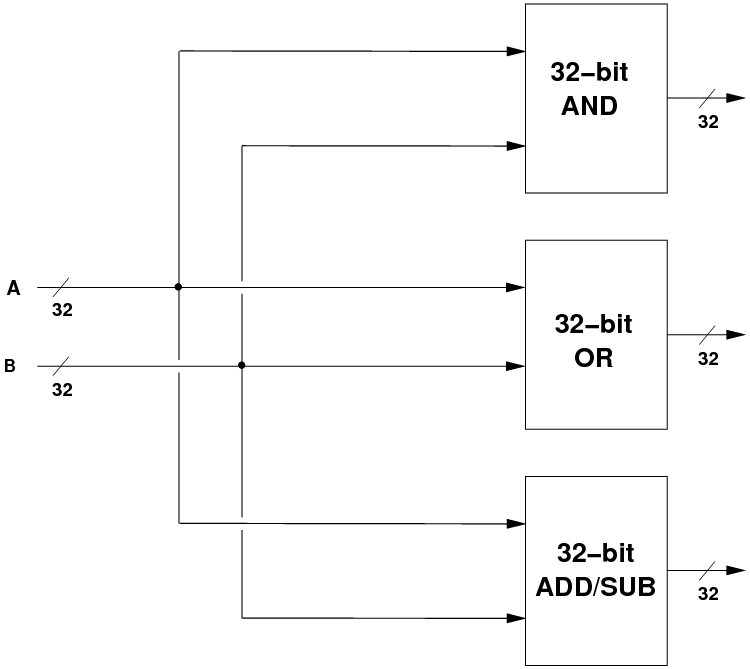
- But, we need to choose which of the three results we want, based on
the two control lines coming into the ALU. We would like:
| c1 | c0 | Result |
|
| 0 | 0 | A AND B |
| 0 | 1 | A OR B |
| 1 | 0 | A + B |
| 1 | 1 | A - B |
- How do we control which of the four operations actually becomes the
result? With multiplexors again.
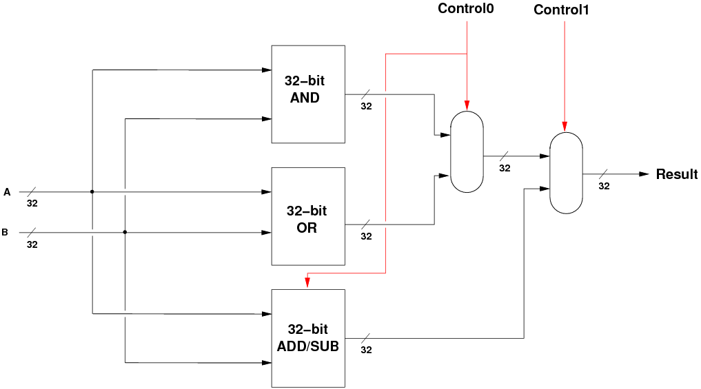
- When c0=0, the ANDORresult is A AND B, and the ADDSUBresult
is A + B.
- When c0=1, the ANDORresult is A OR B, and the ADDSUBresult is
A - B.
- Now we just have to choose between these two results, and that is
done with the second multiplexor, which chooses either the bitwise
logic result or the maths result.
- To finish off, we can draw the three components, the multiplexors
and the zero logic, to reveal the final 32-bit ALU.
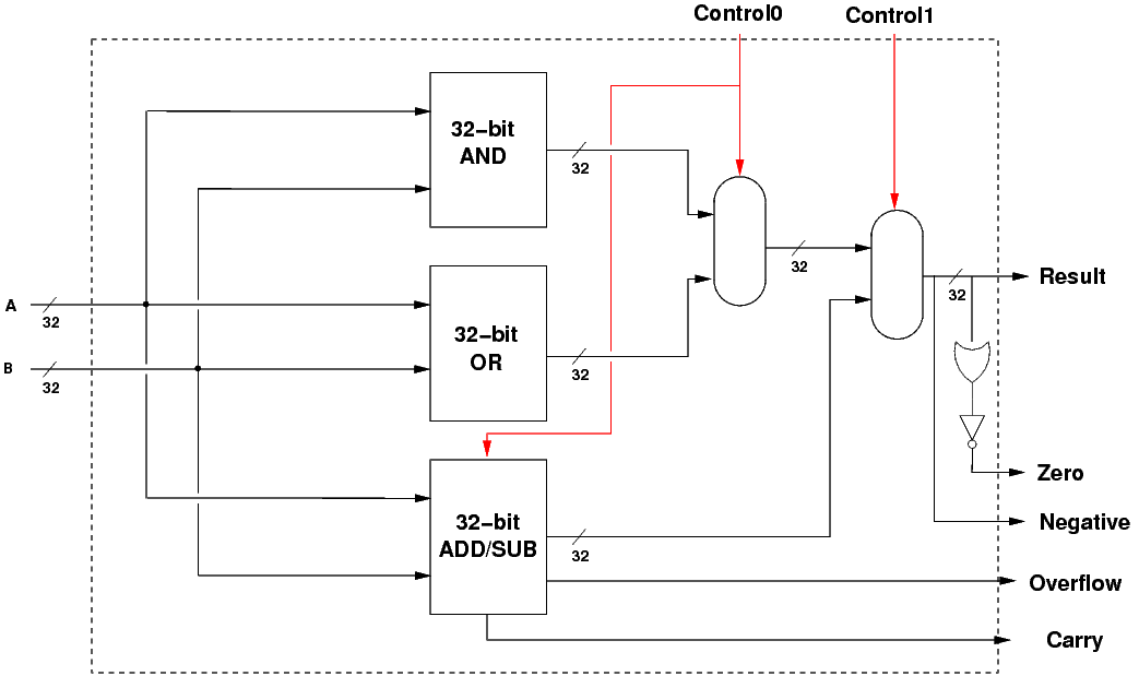
- The dotted line shows the interface to the ALU.
1.11 Implementing the ALU
- Here is the above ALU implemented in Logisim:
ALUweek2.circ
- This is only an 8-bit version, but extending it to be a 32-bit CPU
is simple but tedious.
- Download the file, run Logisim, and open the above circuit.
- Select the Hand icon in the top-left of the Logisim window, then click
on the data inputs and the two control inputs to change their values.
- Try out some additions, a subtraction, some ANDs and ORs, and satisfy
yourself that the ALU works as advertised.
- See if you can put in some input values which cause an oveflow.
1.12 Conclusion
- That's about all we can cover in terms of ALU design in this subject.
- Obviously, real ALUs perform many more operations, and use many performance
optimisations.
- This is just a taste of ALU design, but you should now understand
that:
- an ALU is just a collection of logic components;
- the logic components can be made from ordinary logic gates;
- data can flow in parallel to multiple units;
- everything operates in parallel: several units can produce output
internally;
- control logic, via multiplexors, chooses which output to use as the
result.
- For more interested students, the ALU chapter in Patterson & Hennessy
goes into much more detail and covers more operations such as multiplication
and division.
File translated from
TEX
by
TTH,
version 3.85.
On 2 May 2011, 12:26.


