CPU Memory Management, Context Switching
1 Introduction
- In the last lecture, we saw the reason for user mode and kernel mode,
and the three ways in which a user-mode program can fall into kernel
mode.
- We also saw that kernel mode protects peripheral devices from direct
access by user-mode programs.
- In the last hardware lecture, we are going to see how memory is protected
so as to stop programs from looking at each other's memory and the
operating system's memory.
- We will also see how the CPU can be switched from one running program
to another.
2 Program's Memory Map
- Each user-mode program thinks that it is the only program in memory.
In reality, this is not the case.
- The system (i.e. the operating system using hardware assist) has to
provide this illusion to the program, and also stop the program from
seeing or interfering with the other programs in memory.
- In essence, we have to provide each program with a memory map or address
space.
- Each program wants to see a memory map like the following:
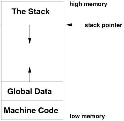
- the machine code starting as low as possible, e.g. from address 0
upwards.
- any global data placed immediately above the code, to provide for
maximum growth.
- the stack placed as high as possible, growing downwards.
- Ideally, each program's address space should take up all of the available
locations on the address bus: if we have a 32-bit address bus, then
the program's address space should be 4 Gbytes.
2.1 Memory Issues
- Achieving the above memory map is difficult for several reasons.
- Firstly, the operating system's memory has to be placed somewhere.
In particular, the code dealing with exceptions, interrupts and exceptions
has to exist. We can't put it in the middle as this would limit the
growth of the global data and the stack.
- Therefore, the OS is usually placed either below the machine code
or above the stack.
- Secondly, what about the memory of all the other programs? What do
we do with it when they are not running?
- On the earliest computers, the solution for multiprogramming was to
swap out to disk the memory of all programs except the one
running. And when switching between programs, the operating system
would swap out the running program's memory, swap in a new program
and start it running again. Of course, this is extremely slow.
- There has to be a better solution, and one that also protects the
OS memory from user-mode programs.
3 Pages
- The current solution to the above memory problems is known as pages.
- We use the following terminology:
- A page is a fixed-size block of memory, positioned
at some starting address in a program's address space. The page size
is set by the hardware design, but is generally around 1K to 8K in
size. The set of pages which a program has access to forms its logical
address space.
- Each page in a program's address space is mapped out to a real, physical
block of main memory known as a page frame. The set of page
frames form the system's physical main memory.
- A hardware Memory Decoder (or MMU) maps the memory addresses
to pages requested by a program to a set of page frames in physical
memory. The decoder can also set protections on each of the program's
page; for example, a program's page may be marked as read-only, read-write,
invalid, or kernel-mode access only.
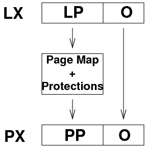
- When a program accesses address LX in its address space, the MMU
divides the address by the size of the system's pages. The resulting
dividend is the logical page number LP, and the remainder becomes
the offset into that page O (i.e LX=LP+O).
- The MMU then maps the logical page to a physical page frame,
by using a lookup table. It then adds on O to get PX, the final
physical address of the location in the main memory.
- As an example, consider a system where pages are 2,000 bytes in size.
A program tries to read from logical location 37,450. The MMU receives
this location number from the address bus. It divides 37,450 by 2,000,
obtaining logical page number 18 and offset 1,450.
- The MMU consults the current page map. Each program has its own page
map. In this page map, logical page 18 maps to physical page frame
115.
- The MMU multiplies page frame 115 by 2,000 to get the bottom address
of the page frame, 230,000. It then adds back on the offset, 1,450,
to get 231,450. Finally, the MMU performs the requested operation
on physical location 231,450.
- From the program's point of view, it has access location 37,450, which
is on page 18. But the MMU has mapped this to physical location 231,450
on page frame 115.
- If the original page has a suitable protection, the memory access
is permitted. Otherwise, the MMU sends an exception to the CPU to
inform an appropriate exception handler of the protection error.
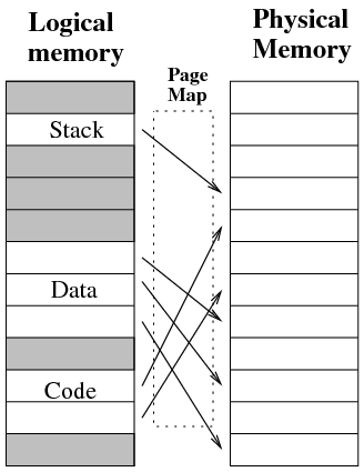
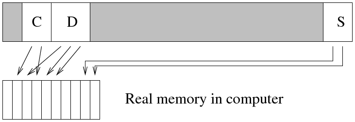
- The page map here is the crucial element that makes the system work.
Although programs see their logical memory as being contiguous, their
page map can spread their logical memory around as a number of separate
page frames in physical memory. For example, a program's memory may
actually be placed in physical memory like this:
- Also note: each program gets its own page map, so the page frames
for several programs can be in memory at the same time, even though
each program can only see its own pages, i.e. its own logical address
space.
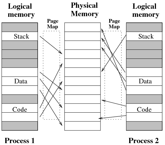
- Each program's logical address space can be the size of the address
bus, even though the computer might not have that much RAM (e.g. only
1G RAM in a 32-bit address bus computer)
3.1 An Example Page Entry
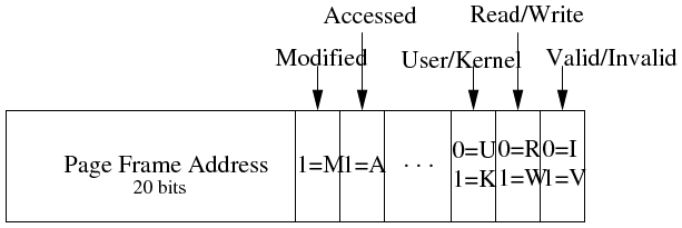
- Here is an example page entry (a single page to page frame mapping)
on the Intel IA-32 architecture.
- On this system, pages are 4K in size, and there are 1,048,576 page
entries in the page map, numbered from logical page #0 up to logical
page #1,048,575.
- Each entry is 4-bytes in size, so a page map for the full 4 Gbyte
address space is 4 Mbytes in size.
- On the left of the page entry is the matching page frame number. So,
if this was page entry #23 in the map, and the page frame address
was 117, then logical page 23 would be mapped by the MMU to page frame
117.
- On the right are the page permissions:
- If the Valid bit is 0, then no page frame has been mapped to this
page, and any access will cause an error.
- Next is the Read/Write bit: if it is 0, only reads are allowed, if
1, writes are also allowed.
- When the User/Kernel bit is 1, access to the page can only be done
when the CPU is in kernel mode.
- Finally, the Access and Modified bits are used by page replacement
algorithms, which we will see in later lectures.
- Note the User/Kernel bit. When one program is running:
- all of the pages that it has access to are marked as readable in user
mode.
- there will be some page entries in the map which point to operating
system page frames. These are needed so that the exception handler
code, for example, will be in the right place when an exception arrives.
These pages are marked kernel-mode only.
- All the page frames (physical memory) used to hold other programs,
and all the page frames which are not being used by anybody, are not
even mapped in the page map. This prevents the program from getting
access to them.
- Note: it should be obvious, but the page map can only be viewed or
modified in kernel mode. If a user-mode program could modify the page
map, then it could map in the memory of other programs.
3.2 Problems of Paged Memory Management
- The MMU logical/physical conversion can be slow, as the page map can
be quite large.
- One optimisation here is to `cache' the last N logical to physical
conversions, as usually the next memory access will be on the same
page as the last one. This is usually done in the MMU hardware with
a Translation Lookaside Buffer (TLB).
- When context switching between programs, the operating system must
`unmap' all of the pages of the old program, and map in the pages
of the next program. If 20 pages have to be unmapped and 30 pages
have to be mapped in, the operating system must send 50 commands to
the MMU. This can be very slow with programs that have a large number
of page map entries.
- The number of mappings the MMU must be able to do can be huge. For
example, if the page size is 1K, and the address space is 4G, the
MMU's page map must hold 4 million page mappings. Thus the MMU's hardware
must be very big.
- And when we do a context switch between two programs, we must save
the page map for the old program out of the MMU, and load the page
map for the new program into the MMU. These operations can be expensive
if the page map is big.
- You may argue that increasing the page size would reduce the number
of mappings, and thus reduce these problems. Later on, we will see
that this will create another problem.
4 Context Switching
- We now have:
- a user mode and a kernel mode for the CPU.
- protections for pages, so that a program can only see its own pages,
and not access the operating system's pages even if they are mapped
in to the program's address space.
- a mechanism to get from user-mode to kernel-mode without allowing
the program to run in kernel-mode.
- the ability to deal with I/O devices by interrupting the CPU (forcing
it to kernel mode), rather than polling the I/O device continually.
- We can finally look at how to switch the CPU between multiple programs
which want to run on the system: context switching.
- Firstly, the term "context". This means the environment that
a program runs inside. For now, it means the address space that the
program has, plus the current state of the program's registers. Later
on, we will extend the meaning of "context".
- Secondly, and more importantly, you should realise that the operation
system does not run like a program!
- The CPU should be running in user-mode as much as possible: the purpose
of a computer is to run programs.
- The OS kernel is only invoked by an interrupt, exception or system
call. It has to handle this as quickly as possible, and get back to
user mode and continue to run a program.
- Now, why do we want to context switch, i.e. switch between programs?
- Because all contemporary systems allow for multiprogramming:
having multiple programs in memory which take turns to run on the
CPU.
- for example, a file system browser, a web browser, a chat program,
a word processor, an e-mail reader etc.
- The act of context switching can only be performed in kernel mode.
Why? Because only in kernel mode can the page map be changed.
- So, what are the steps of a context switch:
- Get into kernel mode.
- Quickly save the old program's registers somewhere, and the address
of the next instruction it was about to execute, so they can be restored
later. This storage area is known as a Process Control Block,
or PCB, and it is stored in kernel-mode memory somewhere.
- Save the mappings in the current page map, also into the PCB.
- Unmap all of the old program's pages from the page map.
- Choose a new program to re-start. Find its PCB.
- Re-map the pages of the new program from its PCB.
- Re-load the registers of the new program from its PCB.
- Return to the next instruction of the new program, and return to user-mode
at the same time.
4.1 Getting Into Kernel Mode
- We can't rely on getting into kernel mode via a system call or an
exception to do a context switch, as this depends on the running program
being co-operative enough to do one for us.
- Instead, we need an interrupt to arrive. Again, how do we know that
this will happen frequently enough?
- The solution is to have a peripheral device which sends interrupts
to the CPU at regular intervals.
- This is done by a clock device or timer, which sends regular
clock ticks (interrupts) to the CPU.
- One way to do this is to have a programmable counter, which counts
the normal system clock cycles:
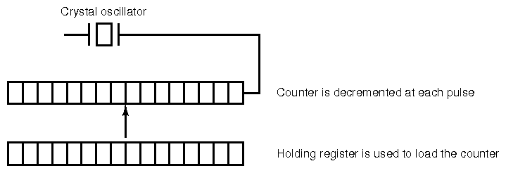
- When the counter is decremented and reaches zero, it sends an interrupt
to the CPU and re-loads the counter.
- For example, if the CPU is running at 3GHz, and the counter is set
to 60,000,000, then a clock tick will be sent to the CPU 50 times
as second, i.e. a 50Hz interrupt rate.
- Typical clock tick rates range from 50Hz up to 1,000Hz.
- We will revisit the concept of context switching in much more detail
once we get to the Operating System half of the subject.
5 Summary of Computer Architecture Half
- We've now covered half the material in this subject. What have we
seen?
- The basic components of a CPU: registers, IR, PC, ALU, multiplexors,
busses, control logic.
- What an instruction architecture is:
- available operations.
- how many operands.
- addressing modes.
- and the difference between RISC and CISC mindsets.
- How the control logic of a CPU can be built: either hardwired or using
microcode.
- How high-level control structures like decisions, loops, functions
are translated to machine code.
- User mode and kernel mode: why both are required.
- System calls, interrupts, exceptions, and how to handle them.
- How I/O is performed: polling or with interrupts.
- How to context switch between running programs.
- We have also learned how to write some simple programs in MIPS assembly
language, using the MIPS ISA.
- Remember: an ISA is an abstraction which hides the
CPU internals, and an interface to use the CPU.
- For the second half of the subject, we look at the system software
which controls the system hardware, and which provides a much nicer
environment for programs to run in: the operating system.
File translated from
TEX
by
TTH,
version 3.85.
On 17 Feb 2012, 07:00.


