System Architecture

(INFT12-212 and 72-212)
Lab Notes for Week 2: MIPS Architecture & Data Representation

1  Introduction

This week we are looking at how data is represented in the MIPS architecture, how data is stored in registers and in main memory, and the basic MIPS instructions to manipulate that data.

2  Twos-Complement Integers

First up, a quick revision of the concept of twos-complement representation. Given a fixed-size grouping of bits, e.g. an bit byte, we want to be able to represent both positive and negative numbers equally as patterns of 8 bits. Positive numbers are easy, we make the right-most bit in the word equal to 1, and each bit to the left is worth twice the bit to the right. Then any bit pattern is the sum of the "worth"s of all the bits. For example, the bit pattern:
128 64 32 16 8 4 2 1
0 1 0 1 1 0 0 1
is worth 64 + 16 + 8 + 1, or 8910. The right-most bit is known as the least significant bit, and the left-most bit is the most significant bit. For negative numbers, we set the most significant bit to 1; for positive numbers it is zero; this ensure that half the bit patterns and positive and half are negative.
However, a negative number in twos-complement representation is not the positive equivalent with the most significant bit set to 1: if 01011001 is 8910, then 11011001 is NOT -8910!
The way twos-complement works is that, when a number and its negative equivalent are added together, the result will equal 0, i.e. the final bit pattern must be all-zeroes.

2.1  Visualising Negative Binary Numbers

My recommendation here is: by all means try to decode a positive binary number like 01011001 by adding the columns together (64+16+8+1), but DON'T try to read or decode a negative number, as it doesn't work.
Instead, visualise negative numbers like a car trip meter (odometer): negative numbers are a certain distance "away" from zero. For example, let's use 4-bit groups for now:
-8 -7 -6 -5 -4 -3 -2 -1 0 1 2 3 4 5 6 7
1000 1001 1010 1011 1100 1101 1110 1111 0000 0001 0010 0011 0100 0101 0110 0111
Starting with 0000, when we move forward 1, we add =0+1 in the right-most column, and as there is no carry, we get 0001.
Now, why is 1111 equal to -1? Because we have to add 1 to get to zero! Starting with 1111, if we move forward 1, we add 1+1 in the right-most column. This gives 210,or 102.We write down the 0 and carry the 1. In the second column, 1+1 gives 0 carry 1. In the third column, 1+1 gives 0 carry 1. In the fourth column, 1+1 gives 0 carry 1 which we throw away. So: 1111 + 0001 gives 0000. This is why 1111 is equal to -1.
Going back to the idea of the car trip meter, the number below 0000 is 9999, because 9999 + 1 kilometre will bring you back to 0000.
Also note from the above table: odd numbers always have their least-significant bit set, and even ones don't.

2.2  Positive to Negative: Algorithm 1

Instead of trying to read a negative bit pattern, here is one algorithm to convert positive to negative, or negative to positive:
Flip all the bits and add 1
Let's try it out: we know that 01011001 is 8910. Flipping the bits gives 10100110. Adding 1 gives 10100111: fortunately there was no carry. So 10100111 is -8910.

2.3  Positive to Negative: Algorithm 2

The above algorithm works, but you have to do binary addition and that can be error-prone. Here is another algorithm to convert positive to negative, or negative to positive:
Scan the number from right to left, leaving all least significant zeros and the first one unchanged. Then flip the remaining digits to the left.
Let's try it out with 01011001. There are no least significant zeros, and we therefore leave the right-most one unchanged. We flip all the other bits. This gives us 10100111, where the bold indicates the untouched bits.
Here's another 8-bit number: 00101100. Question: what is it in decimal? To negate it, we leave the right-most bits and the right-most one untouched, and flip all the other bits, giving 11010100.

3  MIPS Data Types

The MIPS CPU provides us with a lot of flexibility in terms of integer data types. Not only are there four sizes: but MIPS can treat any value as either signed (i.e. twos-complement) or unsigned. Unsigned means that there are no negative numbers, and the most-significant bit is just another power of two to add to make a positive value. For example:
Signed byte: -8910
-ve              
1 1 0 1 0 1 0 0
Unsigned byte: 128+64+16+4= 21210
128 64 32 16 8 4 2 1
1 1 0 1 0 1 0 0

It's worth remembering the ranges of the 8 possible MIPS integer types:
  Signed Unsigned
Byte -128 to +127 0 to 255
Halfword -32768 to +32767 0 to 65535
Word -2147483648 to +2147483647 0 to 4294967296
Doubleword -verybig to +verybig 0 to verybig

3.1  Endianness

For our purposes, the MIPS architecture is little-endian. This means that, for multi-byte data types such as halfwords, words and doublewords, the bytes which hold the most significant bits come last. Let's take the decimal number 25722900410, which is the 32-bit binary pattern 00001111   01010101   00000000   11001100. I've chosen a pattern where each group of 8 bits is different. If this word is stored by the MIPS CPU in main memory at locations 0 to 3 (memory locations are byte-sized), then the number will be stored as:
Location 0 Location 1 Location 2 Location 3
11001100 00000000 01010101 00001111
Or, if we convert into hexadecimal, the 32-bit pattern 0xF5500CC will be stored as 0xCC, 0x00, 0x50, 0xF5, i.e. the little end of the value comes first in memory.

3.2  Data Alignment

The MIPS architecture requires that: This is known as data alignment. You have to be mindful of this, as you can end up with some wasted memory. Consider the following assembly language program which stores several numbers in memory.
         .data
  num1:  .byte    5       # Store 5 as a byte
  num2:  .half    6       # Store 6 as a halfword, i.e. 16 bits
  num3:  .byte    7       # Store 7 as a byte
  num4:  .word    8       # Store 7 as a word

Let's assume that the assembler stores these numbers consecutively, starting at address 0. Here's how the memory would be allocated:
Location 0 1 2 3 4 5 6 7 8 9 10 11
Value num1 unused num2 num2 num3 unused unused unused num4 num4 num4 num4
See that num3 which is a byte can be stored at location 4, but num4 cannot be stored at location 5 onwards, as 5 is not a multiple of 4. We have to store num4 starting at location 8 onwards. Ditto, num2 has to start at location 2.

4  Arithmetic Operations on MIPS Registers

Internally, the MIPS registers are all 32 bits in size, so all the arithmetic and logical operations performed by the MIPS CPU are done on 32 bit values. However, we can choose to perform signed or unsigned arithmetic operations. Here are some of the arithmetic operations:
Instruction Result Comment
li Rd, Imm Rd = Imm Load register with constant value
add Rd, Rs, Rt Rd= Rs + Rt Signed addition of 2 registers
addi Rd, Rs, Imm Rd= Rs + Imm Signed addition of Rs with 16-bit constant
addu Rd, Rs, Rt Rd= Rs + Rt Unsigned addition of 2 registers
addiu Rd, Rs, Imm Rd= Rs + Imm Unsigned addition of Rs with 16-bit constant
sub Rd, Rs, Rt Rd= Rs - Rt Signed subtraction of 2 registers
subu Rd, Rs, Rt Rd= Rs - Rt Unsigned subtraction of 2 registers
sll Rd, Rs, shamt Rd = Rs << shamt Shift Rs left by shamt bits, store in Rd
srl Rd, Rs, shamt Rd = Rs >> shamt Shift Rs right by shamt bits, store in Rd
sra Rd, Rs, shamt Rd = Rs >> shamt Shift signed Rs right by shamt bits, store in Rd

4.1  Task 1

Download this assemby program: wk2add.asm. Open up the MARS simulator and load the program. The code loads 45 into register $t0 and 11 into $t1, add them and stores the result into register $a0. The program then calls the print_int system call to print the result out.
Assemble the program and switch over to Execute view. Single-step the instructions using the Figs/marssinglestep.png 
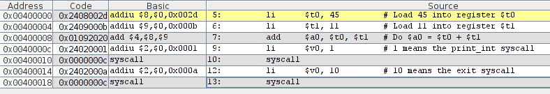
icon, and watch as the two constants are loaded into $t0 and $t1, then as the addition is stored into $a0.

4.2  Pseudo-instructions

In the Execute view, look at the Text Segment sub-window: you should see this:
Figs/wk2fig1.png
The assembler has stored the program's code in memory starting at address 0x00400000. The Code column shows the actual machine code for each instruction in hexadecimal. Note also that the li (load immediate) instruction is not a real instruction: it's a pseudo-instruction. In this case, li $t0, 45 has been converted by the assembler to addiu $t0, $0, 45. Why are these equivalent? Because $t0 = 45 is also the same as $t0 = 0 + 45. Remember, the $0 register always contains the value zero!

4.3  Task 2

Modify the wk2add.asm program. Use the $t0 to $t7 registers, calculate the following into the $a0 register, and print out the answers:
  1. 400 + 17
  2. 100 + 50 + 19
  3. 80 + -5 (use add)
  4. 80 - 5 (use sub)
  5. (10 + 20) - (5 + 6)
  6. something with four numbers and three add/sub operations.

5  Data Overflows

We saw above that twos-complement 32-bit words have a range from around -2 billion up to +2 billion. What happens if we try to add two numbers together to produce a result which is bigger than 2 billion?

5.1  Task 3

Reload the original wk2add.asm program. Modify the code to load 2 billion (2 followed by 9 zeroes) into both $t0 and $t1. Now run or single-step the program. You should see very large hex values being stored in $t0 and $t1. When the simulator hits the add instruction, however, it crashes with this message:
Error in wk2add.asm line 7: Runtime exception at 0x00400010: arithmetic overflow
Go: execution terminated with errors.
With signed instructions like add, if the result exceeds either the maximum or minimum of the signed range, the CPU throws an exception and the program crashes.

5.2  Task 4

Keep the loading of 2 billion into the two registers, but this time change the add instruction to an addu (unsigned add) instruction. This tells the CPU to treat both registers as holding unsigned values. The result will be 4 billion, which is well inside the range for an unsigned 32-bit number.
The program should run and print out a result. Question: why was the result not 4000000000 but some negative number? Hint: the print_int system call expects that the value to print is a signed value.

6  Shift Left, Shift Right

If you take a bit pattern, say 0011, and shift the bits to the left by one (i.e. put a new 0 on the right, discard the leftmost bit), you get 0110. In Java and C, the << operator is the left-shift operator: a << b means shift the bits in a left by b columns.
Converting to decimal, we started with 310 and ended up with 610. Shifting left by one bit doubles the value. Shifting left by two bits will multiply the value by 4 etc. Shifting right has the opposite property: it divides the value by powers of two, discarding the remainder.

6.1  Task 5

Download and load the wk2shift.asm program. Run it and see that 3 is doubled to make 6. Modify the program and try some different numbers and some different shift values. Also try the srl (shift right logical) instruction as well as the sll (shift left logical) instruction.

6.2  Shift Right Logical, Shift Right Arithmetic

The srl instruction always puts a zero bit on the left when shifting right. This is fine for unsigned or positive numbers, but it doesn't work for signed negative numbers: the left-most sign bit which is 1 is shifted right and replaced with a 0. The negative number becomes a positive one!
Try loading a negative number like -10 into $t0, and then doing srl $a0, $t0, 1 which should shift -10 right by 1 and make -5. You will see that the result becomes positive.
The sra (shift right arithmetic) instruction does a shift right, but preserves the sign bit: if it was 1, the new left bit is a 1. This preserves the sign of the result. Try it out and see if it works.

6.3  Multiplication Using Shifts

We haven't done multiplication yet. One way to do this is with left shifts. Consider:
value * 10 == (value * 8) + (value * 2), i.e.
value * 10 == (value <<3) + (value <<1)
Download and load the wk2shiftmult.asm program. Run it and see what it does!

7  Multiply, Divide, Remainder

Doing multiplication by shifting left does work, but it's ugly and there are issues when dealing with signed values. Fortunately, MIPS has instructions which do multiplication, divide and remainder.
Instruction Result Comment
mul Rd, Rs, Rt Rd = Rs * Rt No overflows detected
mulo Rd, Rs, Rt Rd = Rs * Rt Overflows can occur
mulou Rd, Rs, Rt Rd = Rs * Rt Unsigned, overflows
mult Rs, Rt (hi, lo) = Rs * Rt 64-bit multipy result
multu Rs, Rt (hi, lo) = Rs * Rt Unsigned 64-bit multiply result
div Rd, Rs, Rt Rd= Rs / Rt Signed division
divu Rd, Rs, Rt Rd= Rs / Rt Unsigned division
div Rs, Rt lo= Rs/Rt, hi= Rs%Rt Division and remainder
divu Rs, Rt lo= Rs/Rt, hi= Rs%Rt Unsigned division and remainder
rem Rd, Rs, Rt Rd= Rs % Rt Signed remainder
remu Rd, Rs, Rt Rd= Rs % Rt Unsigned remainder
There are a lot of them! If you are reasonably sure that the result of a multiplication will not exceed 32 bits, use mulo or mulou. If the result is likely to be big, use mult or multu, but then you will need to investigate the mflo (move from lo) and mfhi (move from hi) instructions.

7.1  Task 6

Load and run the two example programs wk2mul.asm and wk2div.asm. Modify them to try out the other instructions: mul, mulou, divu, rem and remu.

8  Loading from Memory, Storing to Memory

So far, all of our data has been stored and manipulated in the MIPS registers. But with only 32 registers, that's not enough to hold large amounts of data: consider writing a program which needs an array of 5,000 integers.
To rectify this, we now look at the instructions available to load data from memory into registers, and to store data into memory from registers.
Instruction Result Comment
lb Rd, label Rd = byte value at label Sign extended
lbu Rd, label Rd = byte value at label Unsigned
lh Rd, label Rd = halfword value at label Sign extended
lhu Rd, label Rd = halfword value at label Unsigned
lw Rd, label Rd = word value at label  
ld Rd, label (Rd, Rd+1) = doubleword at label  
sb Rd, label byte value at label = Rd  
sh Rd, label halfword value at label = Rd  
sw Rd, label word value at label = Rd  
sd Rd, label doubleword at label = (Rd, Rd+1)  
move Rd, Rs Rd = Rs  
Some notes to go with this table:

8.1  Task 7

Load the following program and for now just look at the source: wk2loadstore.asm. The program asks the assembler to fill memory locations with these data sizes and values:
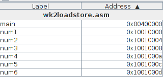
    num1:   .word   7               # Store 7 as a word into num1 location 
    num2:   .word   6               # num2 = 6 
    num3:   .half   -10             # Store -10 into 16-bit location num3 
    num4:   .half   3               # num4 = 3 
    num5:   .byte   64              # num5 is only 1 byte long 
    num6:   .byte   1

Note that I have put things in decreasing size order: this ensures that we don't waste memory due to alignment issues.
Each value is only small and would fit into a single byte: for multibyte data sizes, the remaining bytes should be filled with zeros (or ones for the -10 value). Assuming that the assembler stores these adjacent values in memory starting at location 0, predict which bytes will be all zeroes, all ones, or have the bit pattern of the values shown. Remember that multibyte data is stored in little-endian format! Fill in the following table (on paper) with your guesses.
Location 0 1 2 3 4 5 6 7 8 9 10 11 12 13
                             

8.2  Task 8

Now assemble the program, switch to Execute view, and look at the Labels and Data Segment sub-windows. The assembler has actually stored these values starting at location 0x10010000. You should see this layout of data:
Figs/wk2fig3.png Figs/wk2fig4.png
You can see that num1 and num2 take up 4 bytes each, num3 and num4 2 bytes each, and num5 is only 1 byte. We can assume that num6 is 1 byte, but we need to know what comes next to be completely sure.
Your answer to the data layout question should be:
Location 0 1 2 3 4 5 6 7 8 9 10 11 12 13 14 15
  07 00 00 00 06 00 00 00 F6 FF 03 00 40 01 00 00
Value num1 num2 num3 num4 num5 num6    
Unfortunately, the Data Segment view shows memory as groups of 4 bytes, treated as little-endian words. This means: This is all an artifact of the way the MARS simulator displays groups of 4 bytes as little-endian words. If MARS had a byte-oriented display of memory, you would see the little-endian layout of the words and halfwords properly.

Update

I was able to modify Mars to show the bytes in memory in the actual order that they appear. Under the memory display you should see these controls:
Figs/wk2fig5.png
If you enable the "Hex Bytes" option, then the display of the memory will look like this:
Figs/wk2fig6.png
Now you can see that the value 710at location 0x10010000 is really stored as the 4 bytes 07 00 00 00, and the same for the following words, halfwords and byte values.

8.3  Task 9

Now run the program, see that it loads the data items from memory into registers, peforms the calculation, saves the result back to memory, and the copies the result into the $a0 register for printing.
Play around with the load and store operations, and see what they do.
Question: num3 is stored as the signed value -10. What happens if you lhu (load halfword unsigned) num3 into register $a0 and then print it out? What gets printed out and why? Look at the hex value in $a0 just before it is printed to explain the result.

9  Outlook for the Next Lab

In the next lab, we will look at MIPS addressing modes, and the instructions which change the flow of control and allow you to make decisions and do loops.


File translated from TEX by TTH, version 3.85.
On 25 Nov 2011, 11:15.