31st May 2019, updated 9th June 2019
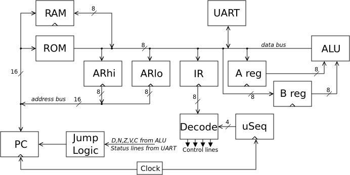
I'm currently fighting a bug in my CSCvon8 TTL CPU. The CPU itself is a fairly simple 8-bit CPU with two registers, RAM, ROM, ALU, UART; it uses microcoding to decode the instruction and execute it across several phases. The overall architecture looks like this:
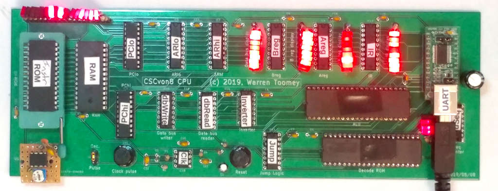
As a whole, the CPU is working amazingly well. The architecture seems solid. I designed the PCB and had it fabricated as my first PCB, and there haven't been any wiring issues with it. Here's the fully populated PCB:
All the instructions in the CSCvon8 instruction set are working well except the jump instructions. Most of them are fine, but some of them are exhibiting the behaviour where the program counter (PC) jumps to some strange address, even when a jump isn't required.
I first noticed this only when I started to read input from the UART and my first ideas were some UART-related issue. But I'm pretty sure that the UART is only tangential to the core problem.
Let's look at the structure of the jump logic before I get on to the details. The ALU in the design is actually an M27C322 2Mx16 EPROM with an 80nS access time. The ALU isn't clocked: the inputs are the A and B register values and a 5-bit ALU operation.
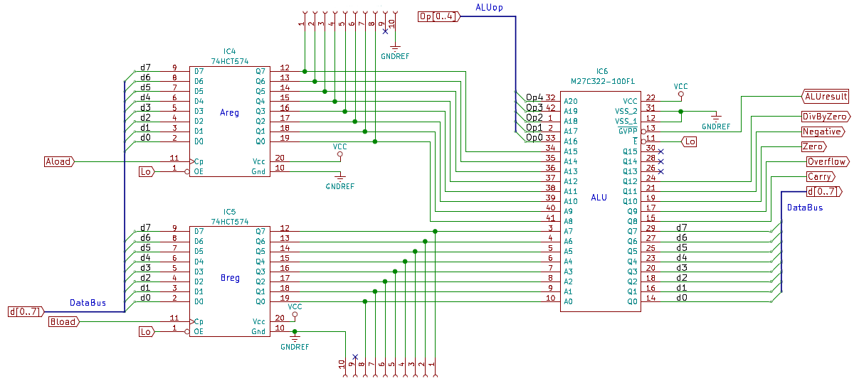
The ALU output is an 8-bit value which can be placed on the data bus, and five status values: (D)ivide by zero, (N)egative, (Zero), o(V)erflow and (C)arry. The ALUresult# line asserts these values when low, or puts the ALU into high-Z output when high.
The ALU status values, along with two UART status values, go to the Jump logic chip. This is a 74HCT251 8:1 multiplexer (bottom right below):

The three JumpOp lines come from the microinstruction Decode ROM and select one of the eight status lines. The selected line is inverted and becomes the PCload# line on pin 6 of the 74HCT251. This PCload# line is connected to the two 74LS593 register/counter chips which form the PC in the CPU. When PCload# is low, the 74LS593s load their value from the address bus. Now, this is either the PC itself, or the value of the two Address Register chips (the 74HCT574 chips on the left of the above diagram).
Now, the 74HCT251 multiplexer is a combinatorial chip and is not clocked. So, we need to ensure that the PCload# line only goes low when we do want to "jump" the PC. This is done by having non-jump instructions set JumpOp to zero. This selects the Lo input on pin 4 of the 74HCT251, which is inverted and sets PCload# high.
We also have to ensure that the Address Register is asserted on the address bus when we want to do a jump. We achieve this by setting the ARena# line low. This line goes to pin 19 of both PC chips and pin 1 of both AR chips. When low, the AR value is enabled on the address bus; when high, the PC value is enabled on the address bus.
Here is the microcode of the JEQ instruction: jump the PC to a new value if the A and B registers are the same.
71 JEQ: MEMresult AHload PCincr         # Load AR from the two bytes
        MEMresult ALload PCincr         # after the '71' instruction byte
        ALUresult A-B ARena             # Ensure that the 'A-B' value is
        ALUresult A-B ARena             # on the data bus, the Zero line is
        ALUresult A-B ARena             # set, and AR is on the address bus
        ALUresult A-B ARena JumpZero    # Set PCload# low if result is zero
                                        # This will cause PC to load AR value
        uSreset                         # Reset the microsequence back to zero
You will notice that the ALUresult A-B ARena microsequence is repeated several times. This is my attempt to work around the jump bugs. I hypothesised that the AR value and the Zero status line need to be set well before we set the JumpOp to JumpZero (value 3). I'm pretty sure that this is only masking the problem and not eliminating it.
Here's the smallest assembly program that I have which exhibits the buggy jump behaviour:
start:  NOP
        JIU .                   # Loop until UART data is available
        INA                     # Read in one byte from UART into A
        LCB '?'                 # Set B to ASCII value of '?'
        JEQ print1              # If A is a '?', jump to print1
        OUT '*'                 # Otherwise print a '*'
        JOU .                   # Wait for output to clear
        OUT '\n'                # and print a '\n'
        JOU .
        JMP start               # Jump back to the start

print1: OUT '1'                 # A was a '?', so print a '1'
        JOU .
        JMP start               # and jump back to the start
Any time the user types a '?', a '1' is output. For any other keystroke, a "1\n" will be printed.
I can clock my TTL CPU with a 555 circuit (DC up to about 50kHz), or with a 1MHz or 3.57 MHz oscillator. For all these speeds, here is what I'm seeing:
Thanks to Tim Rudy, I've been able to model my TTL CPU in Verilog with 7400-series chip models that have the typical propagation delays of the real devices. So here is what the JEQ instruction should do when the A and B registers have the same value:
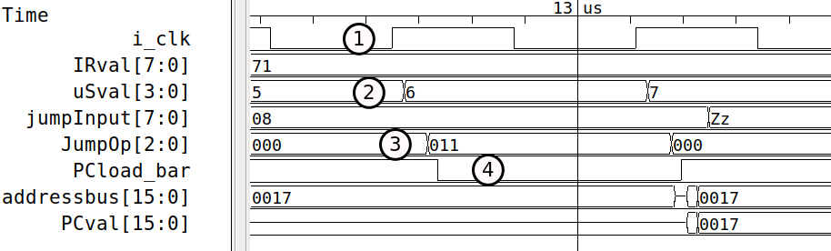
The system clock goes high at point 1. We are running instruction $71 which is the JEQ instruction. The microsequence phase value increments to 6. This means that we already have the Zero result (JumpInput $08) from the ALU A-B operation coming into the 74HCT251 multiplexer. Ditto, the address bus already has the AR value of $0017 on it.
With the microsequence phase value at 6 (step 2), there is a delay for the Decode ROM to output the control lines for the new microinstruction which is ALUresult A-B ARena JumpZero. The only difference in this microinstruction from the previous one is that JumpZero is now being asserted.
Once the Decode ROM value changes, the JumpOp control value changes at point 3 to assert JumpZero. This causes the PCload# line to drop at point 4, after a short delay. The PC loads value $17, but because ARena# is low, it's output is high-Z. We don't see the new PC value until partway through microinstruction 7 where ARena# goes high.
And here is the same set of waveforms when the input is not a '?' and the jump isn't taken:
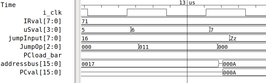
PCload# stays high and the PC value doesn't go to $0017 but stays at $000A which is the value after loading the two Address Register bytes into the two AR chips.
I've tried to diagnose the hardware with the only logic analyser that I have, a Bitscope Micro. However, this only has a 20MHz bandwidth and this means that it's incapable of resolving logic changes below about 50nS.
I have two hypotheses for the bug. Obviously, the PC chips are loading a value when they should not be. This seems to indicate that the PCload# line is going low enough to cause a load. But, as the new PC value isn't the AR value, perhaps this is a very short change: not enough to load the proper AR value, but enough to change some of the internal flip-flop values in the 74LS593 chips.
One hypothesis is that noise is somehow getting on the PCload# line between the multiplexer and the two 74LS593 chips.
A second hypothesis is that the JumpOp control value does not change cleanly from $00 (no jump) to $03 (JumpZero). Remember that JumpOp is being generated by a ROM chip. It is possible that, as the inputs to the ROM change, the ROM chooses a different internal row and column. There may be some different internal delays between the row and column, and so the ROM's output may have some intermediate value as it goes from $00 to $03.
If this is the case, perhaps the intermediate value is JumpNeg. When the user input is below the '?' value, the ALU Negative status is true. This may be temporarily negated by the intermediate JumpOp value, causing a glitchy drop in the PCload# line, causing the PC to load a strange value.
Right now, I can't determine which, if either, of these hypotheses are true. I have found a workaround; I've put a 15nF capacitor across the PCload# line and Vcc. I'm guessing that this is absorbing the glitchy drop in the PCload# line, but any real low PCload# value will make it to zero before the mid-point of the clock cycle.
To get conclusive evidence for the bug, I've ordered a DSLogic Plus USB-based Logic Analyser. This has 16 logic channels, and I can sample 4 channels at 400MHz, 16 channels at 100MHz. That should give me 2.5nS resolution on four lines, enough to see the glitch on the PCload# line.
If the problem is definitely a glitch, my best solution will be to find the smallest capacitor to absorb the glitch but drop the line for real PCload# values. I'll update the blog when the analyser arrives.
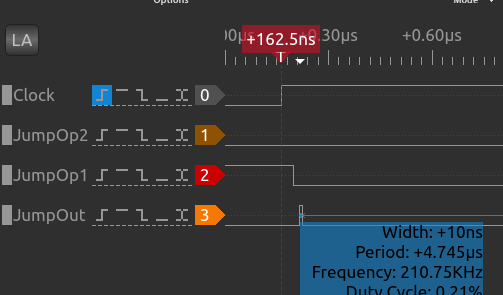
The glitch is revealed with the logic analyser as shown by the waveforms above. It's occurring when the JumpOp lines return to zero. I thought it was happening in the ROM output, but in fact all the ALU status lines and the JumpOp lines are fine. It looks like the 74HCT251 glitches as the three select lines change.
The solution is to replace the 74HCT251 with a 74HCT151, and use the system clock to only enable the output during the second half of the clock cycle:
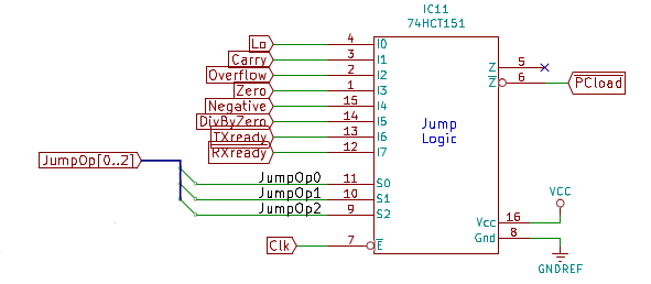
This ensures that the PCload# value stays high until mid-cycle and only drops if there really is a jump to perform. With this change, my CPU is now running solidly at 3.57MHz.